Control of a 5-Link Biped Using Quadratic Polynomial
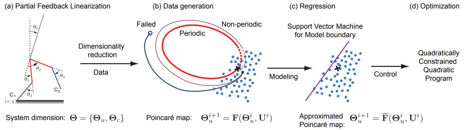
To walk over constrained environments, bipedal robots must meet concise control objectives of speed and foot placement. The decisions made at the current step need to factor in their effects over a time horizon. Such step-to-step control is formulated as a two-point boundary value problem (2-BVP). As the dimensionality of the biped increases, it becomes increasingly difficult to solve this 2-BVP in real-time. The common method to use a simple linearized model for real-time planning followed by mapping on the high dimensional model cannot capture the nonlinearities and leads to potentially poor performance for fast walking speeds. I developed a framework for real-time control based on using partial feedback linearization for model reduction, followed by a data-driven approach to find a quadratic polynomial model for the 2-BVP. This simple step-to-step model along with constraints is then used to formulate and solve a quadratically constraint quadratic program to generate real-time control commands. We demonstrate the efficacy of the approach in simulation on a 5-link biped following a reference velocity profile and on a terrain with ditches.
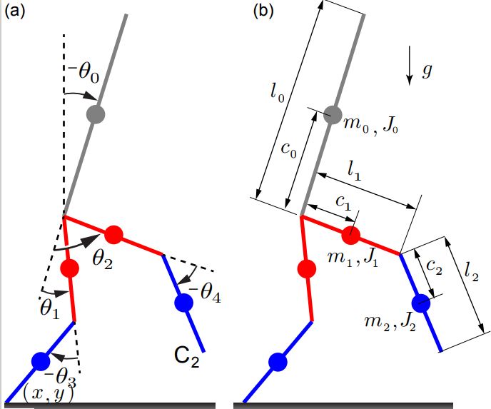
Used a 2D, 5-link biped model with four actuators (one in each hip and one in each knee). The model is under-actuated as there are five DOFs (with the addition of torso position) but only four actuated ones. The physics parameter such as link mass and inertia were approximated to those of the average adult male. The simulator was developed in MATLAB where I used two sets of equations for the simulation model.
Equations
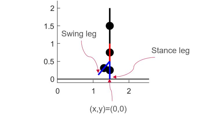
Using Euler-Lagrange’s method I formulated 7 equations of motion for 7 states (x, y, Θ0, Θ1, Θ2, Θ3, Θ4). The first equation used in the simulator is the equation of motion for the 5 DOF states. This equation is used during the single stance phase where one foot is on the ground and the model behaves like an inverted pendulum.
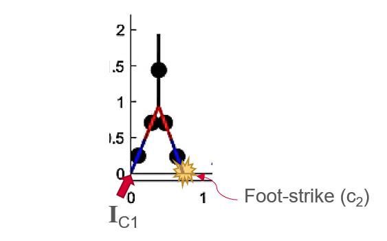
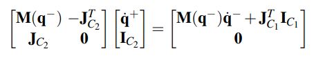
The single stance ends and the foot-strike phase begins when the swing foot C_2 touches the ground. It is assumed that the trailing leg pushes off with an impulseive force I_C1 along the stance leg assimlating ankle push-off. Using the assumption that energy and momentum are conserved and integrating the EOM for the 7 states and taking he limit as time –> 0 the footstrike equation was derived to solve for the states after collision.
Simulator
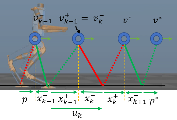
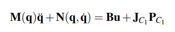
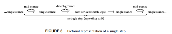
The figure below shows the general equation describing a single step. the repeating unit, that starts and ends at mid-stance.
- Phase 1: Single stance equation integrated until foot-strike
- Transition 1: Occurs when swing foot (c_2) touches the ground.
- Phase 2: Foot-strike equation is applied and legs are swapped.
- Phase 3: Single stance equation integrated until midstance.
- Transition 2: Occurs when biped is in midstance (Θ0+Θ1=0)
Controller
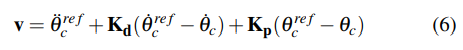
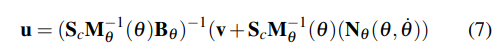
As the model is underactuated, the states chosen for control are the swing leg hip, torso, and both knees. Use partial feedback linearization (PFL) to balance nonlinear terms and simplify the controller (Eq. 7). PD control (Eq. 6) was added for reference acceleration, velocity and position tracking of the states.
Poincare Map Approximation
The goal is now to develop control for walking speed and step length by using as control inputs the step angle and impulse at foot-strike. This could be done by looking at the Poincare Map (Eq. 9) which can be developed by integrating the simulation equations from one mid-stance to the next. The Poincare Map could then be used to discover which control inputs give the desired outputs. Given the complexity and computation time associated with integrating the equations of motion a number of times until a solution is reached, an approximation of the Poincare Map was developed. Continue from here.